My follow-up to the Automatypewriter is another physicalization of a classic videogame: I’m building a playable, mechanical Pac-Man cabinet, called “Pac Machina” (subscribe to my RSS feed if you want to follow my progress!). Of course, essential to a Pac-Man game is Pac-Man himself, and Pac-Man isn’t Pac-Man if he doesn’t chomp. I needed a mechanism for that and it had to be as simple as possible (i.e. no servos or stepper motors). So, after some trial, error, and trigonometry, I built a clockwork Pac-Man. (Note that all images on this page can be enlarged by clicking on them.)
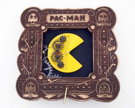
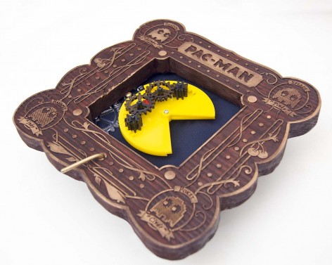
I call it the Pactuator. I kind of fell in love with the little guy, but it’s going to be a (long) while before the game is ready. In the meantime I wanted a nice way to display and play with it (and keep myself inspired to finish the full project). To that end, I drew up a feeble pastiche of a Victorian frame with a Pac-Man motif, laser engraved it in some wood, and made a little display, complete with a hand-crank.
I’ll cut to the chase and briefly explain how it works. If you’re interested, I describe the design, prototyping, and case build in detail below.
How it works
The heart of the mechanism is based on a five-gear loop. Normally, a gear loop will only turn if it has an even number of members; odd numbers of elements will make it jam, since the gears are trying to turn in both directions at once (see here for more explanation). The trick in this mechanism is that the drive gear (in red on both Pac-Man and the schematic) only has teeth on one side (actually four ninths, but who’s counting). It engages only the top gear for half its rotation, and only the bottom gear for the other half. The driven gears switch their direction of rotation every time the drive gear switches from engaging the top to engaging the bottom (and vice versa).
Getting One for Yourself
I don’t really enjoy building the same thing more than once, so I’m not sure if I’ll make more. I might make kits, but it’s a little finicky to assemble. At the very least, before I sell it in any form, I want to make sure it doesn’t fall apart or break after a couple weeks. If I can make them sturdy enough I might try to make some available to fundraise for Pac Machina. (NAMCO BANDAI sent me a nice note politely asking me not to sell these in any form, so I’m afraid I won’t be doing that unless I can get their permission.) I’d also consider interesting trade offers, since other unique things are so much more interesting than money.
If you’d like to make me an offer, or if you’d just like to be notified if I start selling kits, please get in touch!
Design & Prototyping
I’ve been a mechanical watch nerd for a long time so designing my first mechanism, even a simple and primitive one, was very exciting. The goal was to create a mechanical Pac-Man that opens and closes its mouth when you give turn a crank. I had a few requirements:
- Turning the crank continuously would cause both opening and closing (i.e. no back-and-forth cranking), so that it can be driven by a simple motor
- The mechanism had to fit entirely inside Pac-Man’s profile
- The mechanism should work regardless of orientation (so it can be used vertically on a wall or horizontally on a table)
- I wanted the whole thing to be as small as possible, for the scaling of Pac Machina (the prototype ended up having a 3 inch diameter, but I think I can shrink it a little more)
Essentially, the Pac-Man mechanism is all about transforming continuous rotary motion (the crank) into oscillating rotary motion (the mouth). The “easy” way to do this is with a cam and follower mechanism, but I had a few problems with that: I couldn’t rely on gravity because it would restrict the orientation, and I didn’t want to add in a spring because, well, it was too difficult. In retrospect, there are ways I might’ve made a cam work, but I don’t regret the direction I took.
My first mechanisms were all based around converting continuous rotary motion to oscillating linear motion, which would in turn drive the oscillating rotary motion through a pair of linkages. I started out using a mechanism called a Scotch Yoke to convert rotary to linear. The first couple prototypes were made out of cardboard and nails, and worked well enough to continue with this design.
Next, I drew the pieces in the free version of Sketchup (using the free involute gear and DXF exporter plugins) and used the laser cutter at Site 3 to cut them out of scrap acrylic. At this point I was using nails as shafts, cardboard scraps as makeshift “bolts,” and a block of styrofoam as a mounting base.
It was clearly time to upgrade to real hardware, so I picked up some real nuts and bolts. I also realized that I could save an awful lot of scrap plastic if I didn’t cut out the entire Pac-Man body for every prototype, which is why this next guy looks like Swiss cheese.The smallest bolts that hardware stores carry are still pretty big relative to the scale of the mechanism and that quickly became a limitation, so I made a trip to my local hobby shop to buy some small (2-56) nuts and bolts, that were used (and reused) in all future prototypes.
At this point, the shortcomings of this mechanism started to become clear. If you turned the crank quickly it looks pretty good. The problems became really apparent when you slowed it down: turning the crank had some bad catches, the mouth wouldn’t always close all the way and, worst of all, the mouth would droop a little bit open due to gravity. I played with this design a little bit more (exchanging the Scotch Yoke for a much simpler piston) until I decided that, to get the precision I wanted, I would have to use gears.
On the positive side, I knew gears would look much cooler in the final product; on the downside, I was afraid that they would be too complicated. If I had gone with my initial gear-based design, that might’ve proven true: I was still planning on converting rotary to linear and back to rotary. The plan was to use a Cardan gear to convert rotary to linear, and have that fixed to a pair of racks that would drive the mouth-pieces. I got as far as building the Cardan gear (which, incidentally, looked awesome, and I hope to incorporate one into a future project). Then I took a step back and realized that the real problem was the “middleman” of the oscillating linear motion, whether it was geared or not. I started thinking of ways to get oscillation without using any linear components. Ironically, my inspiration came from this mechanism, which is designed to create linear motion.
While I’m sure there are other, better mechanisms out there for generating oscillating rotary motion from continuous rotary motion, and in fact somebody has probably created this one before, I’m still pretty pleased that I managed to come up with it on my own. Because the “half” gear is the figurative heart of the mechanism, and because it actually looks somewhat like an anotomical heart, I decided to make it red in the final product to emphasize its importance and make it a little more noticable.
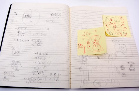
Once I had the idea for the mechanism it took a bit of geometry and trigonometry to figure out the smallest Pac-Man relative to the mechanism size, and then some trial and error to get everything working just right.
The Case
The Pactuator (or a version thereof) will eventually feature in Pac Machina, but I also like it enough on its own that I wanted to have a way to display it and play with it. Although my artistic skills leave much to be desired, I drew a Pac-Man motif that I was happy with and engraved it on a block of pine using the Site 3 laser.
I then cut the outer edge with a scroll saw (my first time using one!) and the inner edge with a jigsaw (also my first time using one!), stained it, and, using the delightfully-named “Rub ‘n Buff,” added some metallic highlights to help bring out the detail. I “antiqued” it, which is a fancy way of saying “no, those aren’t mistakes, they’re intentional so it will look old!” For the inside I used some satiny blue fabric to give it that “precious object” feel, and also to be evocative of the blue maze walls in the original game.
I like being able to hold the mechanism in my hand, so I wanted it to be easily removable (it didn’t seem right to have it captive in that little box!). On the other hand, it also needs to be secured well enough that the crank won’t push it out of alignment. I couldn’t find anything pre-fabricated that exactly met my needs so I designed my own magnetic standoffs: I put a pair of rod-shaped magnets in the box, and I attached disc-shaped magnets to the back of Pac-Man. The magnets on Pac-Man are behind a layer of plastic to reduce the pull (these rare-earth magnets are ridiculously strong), and there’s also a plastic ring into which the rod fits to keep it from sliding laterally. They work really well!


Cool mechanism, but I think it needs a spring so you can wind it up and let it chomp by itself.
Thanks Ilya! This is essentially a prototype that I put in a fancy box: it will definitely chomp by itself eventually, but I don’t want to spend too much time adding bells and whistles now.
I was wondering how the gears seemed to switch direction while the turning of the crank never did. Clever.
I love this thing.
I appreciate how you included the diagram showing how you got the 5 gears to work together. Brilliant!
You are a credit to your race. Exceptional, and may I say elegant. There can be no doubt that you would have done just fine in the steam punk era.
This is dead cool. Very clever mechanism that’s worthy of praise. It’s big isn’t it? Is the cabinet going to be wall-sized?
It’s actually not very big: Pac-Man’s diameter is about three inches. In the real thing I hope to get it closer to two inches, which means that the playing area will be about 2.5 feet by 3 feet. So, significantly larger than the monitors in old arcade cabinets, but not quite as big as a modern big-screen TV.
I know you have to be modest and such, but I think the artwork on the frame is brilliant! To me, it almost overshadows the Pactuator mechanism itself… almost ;)
Also, thanks for introducing me to robives.com and its wonderful collection of paper mechanism models! That’s a keeper for sure.
Thanks! The art came out better than I expected I’d be capable of, but the problem is it will never quite live up to the vision I have in my head.
Rob Ives’ site is indeed wonderful, and I’m happy if I introduced it to even one new person.
Your gear mechanism is very innovative. You might consider a crank-rocker linkage in lieu of the gears. The connection to the base of the rocker linkage would be concentric with pac man’s body. It would run more smoothly than your gear train and be more easily miniaturized since you would like to reduce the size of your pac man.
Thanks! I have considered a crank-rocker linkage. The reason I haven’t tried it is that, frankly, I find it more difficult to visualize, and I’m designing these mechanisms by hand.
That said: believe it or not, the motion of the gear mechanism is perfectly smooth. The apparent jerkiness in the video is all due to the gears in the box sticking, combined with the difficulty of turning the handle while not interfering with the camera.
I find it surprising that you are able to visualize your mechanism and have trouble with a simple crank rocker! Here’s a crank rocker with the paths of each linkage mapped out.
http://upload.wikimedia.org/wikipedia/commons/9/9a/Linkage_four_bar.png
Give the crank rocker a shot. I think you’ll be pleasantly surprised. In the diagram above linkage members S and L are the only ones you have to fabricate. Member Q would be the non-moving part of pac man’s head and member P would be the moving part of pac man’s head. The joint between S and Q (S-Q) is your drive shaft which is rigidly coupled to member S to cause it to rotate. Joint Q-P is at the bolt base of pac man’s mouth. Joint P-L is somewhere on the moveable part of pac man’s mouth and some distance away from Q-P. Play with the linkage lengths till you get the motion you want(or look up crank-rocker tables). Does this make sense?
Don’t get me wrong: I understand how it works, I just don’t have the same intuition for it that I do with gears. It’s the “play with the linkage lengths” step that I’m trying to avoid. At this point I’m pretty happy with how the geared mechanism works, both functionally and aesthetically. If it gives me problems down the road, though, I’ll definitely reconsider.
Hi
I am from Norway and would like to have a look at your gearing :-) is it possible to send a copy in some vectorised format ?
/John
I second that. Have you considered uploading your design files to thingiverse.com. People there would really appreciate this and they can donate to your project.
Regarding selling them, your real issue is promoting it as a “pac-man”. Without that, it’s just a geared thingy that opens and closes. Sell it as a “mechanical grape squasher” and you’d be good to go. Let people make their own “pac-man” frames if they so desire.